Scroll for More
⇩
A new architecture for
A new architecture for
A new Architecture For
Scroll Down
⇩
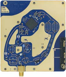
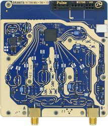
LA9310
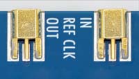
Si5510
i.MX 8M Plus
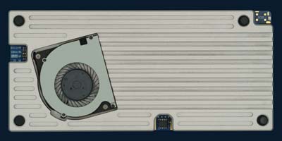
Enclosure
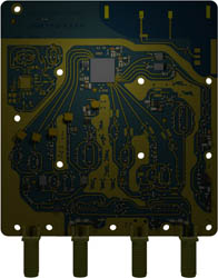
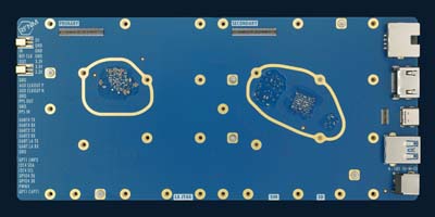
Backside
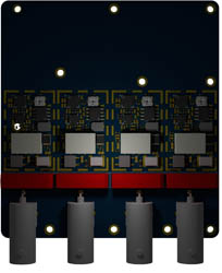
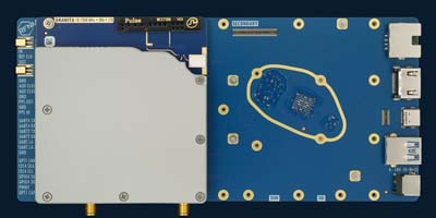
Daughterboards
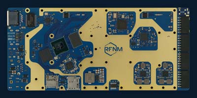
The star of the show.
Eight ADCs and two DACs running at 12-bit and 153 MSPS, plus 80 GFLOPS of VSPA-2 DSP power.
Datasheet
Eight ADCs and two DACs running at 12-bit and 153 MSPS, plus 80 GFLOPS of VSPA-2 DSP power.
Datasheet
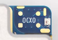
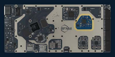
Infrastructure-level clocking.
47 femto seconds of RMS jitter, 18 outputs and a digitally controlled oscillator for zero-ppm frequency errors.
Datasheet
47 femto seconds of RMS jitter, 18 outputs and a digitally controlled oscillator for zero-ppm frequency errors.
Datasheet
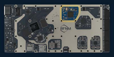
ARM Cortex-A53 and M7 for real-time applications.
Latest generation NXP processor to foster an ecosystem of onboard applications.
Datasheet
Latest generation NXP processor to foster an ecosystem of onboard applications.
Datasheet
Machined heatsink
A CNC machined heatsink with active dissipation protects the electronics from damage and interference.
A CNC machined heatsink with active dissipation protects the electronics from damage and interference.
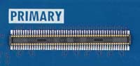
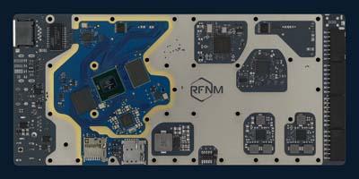
RFNM Interface
An I/Q based IF interface allows a variety of daughterboard-specific applications.
An I/Q based IF interface allows a variety of daughterboard-specific applications.
Daughterboards
The motherboard connects directly to a new set of compatible boards.
The motherboard connects directly to a new set of compatible boards.